Energy Meter - Feb 2019
Let's measure some power :)
DESCRIPTION
This is a school group project, it was made during a course about working in a design office.
In this project I mostly worked on the wifi connectivity part of the project and en low noise opAmp portion.
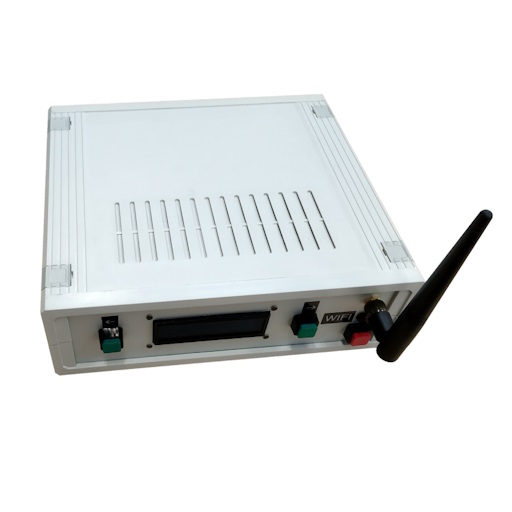
Final product
CHASSIS
The chassis is a generic project box that the university had in stock, the plastic body was left as-is, only the front and back aluminium panels were drilled to accomodate our components.
ELECTRONICS
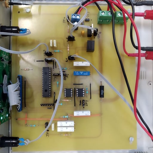
We designed the PCB in Eagle, I had to create a custom library for the ESP-01s module as there were none available at the time.
We decided to use two AD711 opamps for sensing the voltage across the shunt resistor. We used two because we expericenced severe non-linearity when using high amplification, this way we have two stages of near linear amplification.
The PIC is responsible for the measurement, menu navigation and LCD display, this is a project constraint set by the teacher.
We then added WIFI by having the ESP communicate via UART with the PIC.
I made the ESP program and used SPIFFS to store a crude CSS and js for asynchronous calls.
The UI can be viewed inside a web browser on both desktop and mobile.
CALIBRATION
As you may have guessed, we made a calibration map for the PIC.
We used out best spreadsheet and measured point using the lab equipment of the university.
Two isolated DC power supplies were used to produce the max voltage and we drew I/V curves by modulating power using a load bank rheostat.
The final calibration map was set inside the PIC memory.
REPORT
The project report is available for download here :
DOWNLOAD
EDIT: I know that there should be a ground plane but there are none, we were inexperienced at the time of conception I guess.
Photo of our bare board
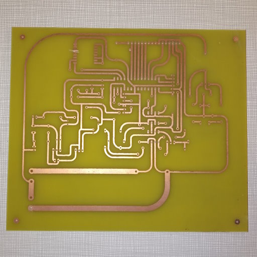
Photo of the assembled board