Lightfighters - Mar 2022
Quite a cool school project I must admit.
DESCRIPTION
This is a school group project, it was made during a course on agile project management.
I have a lot to do with the completion of the project, I designed almost all of the hardware to fit the needs of our client.
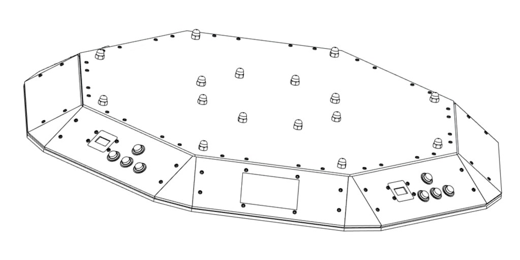
Wireframe render
CHASSIS
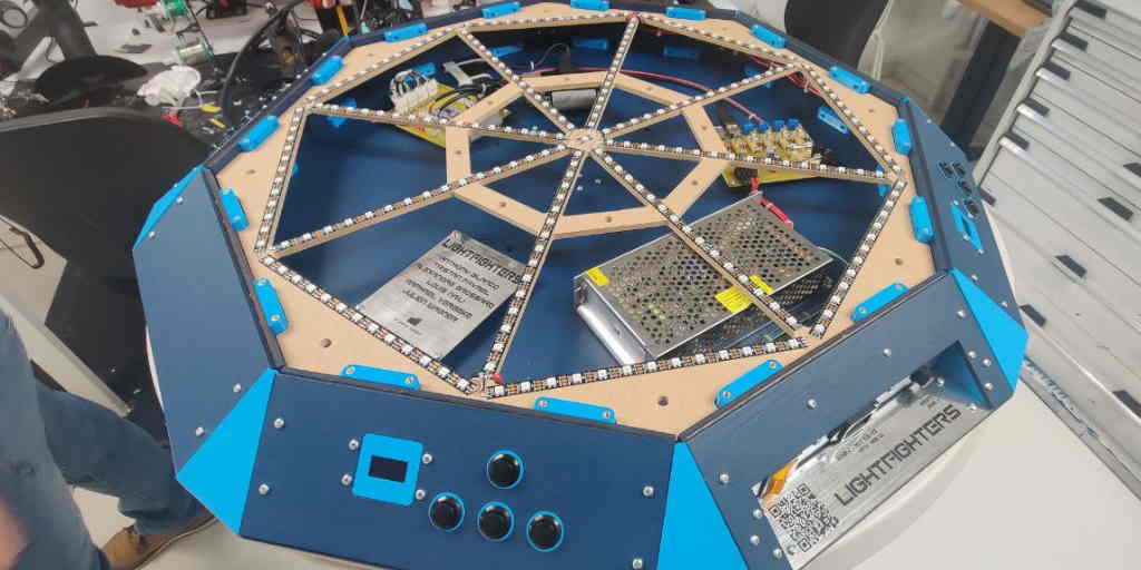
The chassis is made from laser cut 5mm plywood, many many custom 3d printed parts, a massive CNC cut 6mm MDF sheet and a big sheet of acrylic also CNC cut.
I designed all of this in fusion360 and made all exports to use the laser cutter and CNC, we used the CNC at HEI, big thanks to them.
The assembled project file was very slow on my laptop ^^
Photo of the assembled project
ELECTRONICS
One of the requirements was that we would need to be able to add game modes from the Git repository of the project, thus a raspberry pi board was used.
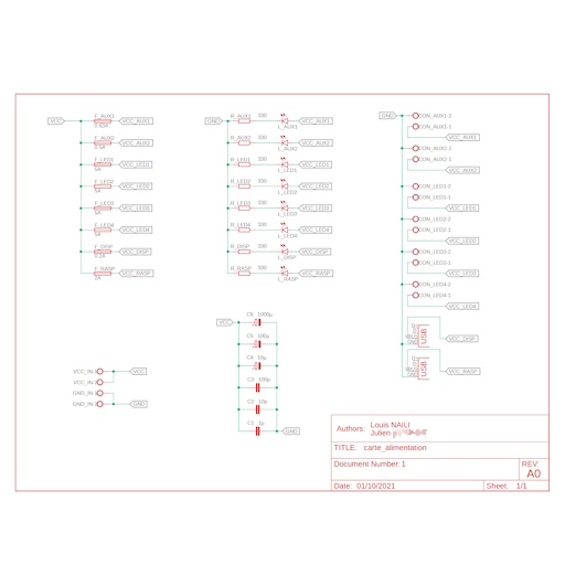
The LEDs could draw a massive current if all lit up at the same time, for this reason I decided to make the strip into sections and have a little filtering and a fuse for each section.
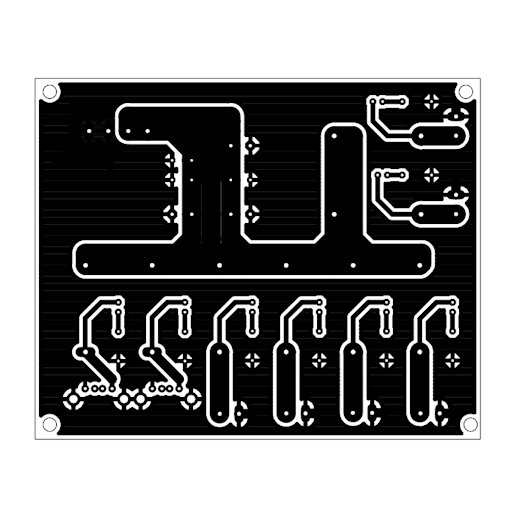
I taught a peer who had never done PCB design before how to use Eagle, here is the fuse PCBs. Each fuse has a LED indicator, if a fuse goes out then the LED also goes out, although we never encountered this issue it was pretty nice and the board looks very nice IMHO.
Schematic of the fuse board
Board view of the fuse board
The Raspberry pi connector is a 40Pin, I desides to use an old IDE cable to bridge the PI to a separate board and have all electronics there.
The main board is designed around a TCA9548, this is an i2c MUX, each player around the board has his own little OLED display for his specific info, these OLEDs can only have two I2C addresses and we wanted to have 4 displays on the same bus. For this reason we used the same address on all displays and made the MUX do all the work (this would later prove to be harder to handle).
Other than the I2C bus, the main board allows us to connect the user buttons as inputs to the PI GPIO, a signal that goes to the led strip, and a power led for each voltage rail.
Power to the oled displays is handled through dedicated connections on the board.
EDIT: In the final project, we were running out of time and the MUX was posing problems with the software on the Pi, I designed a hack that would enable us to have a working product for our demo. The hack was simple, the ribbon cable coming from the PI to the main board was cut and I added an arduino that would serve as an interface between the PI and the MUX. The PI talks to the arduino using the hardwrae uart of the PI and the arduino uses its internal I2C to drive the mux. This acts as a frame buffer, this also enables us to seemlessly update things assynchronously on the OLEDs and on the PI. Very dirty but it works :) I had not documented the hack prior to now, I am not even sure everyone in the team understood what was done there ^^
Anyways, here is the main board :
Schematic of the main board
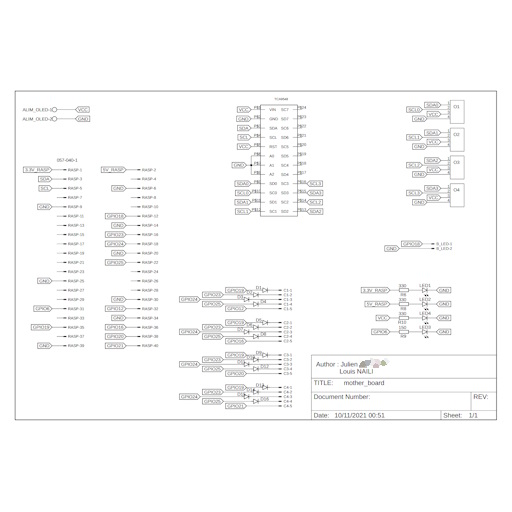
Board view of the main board
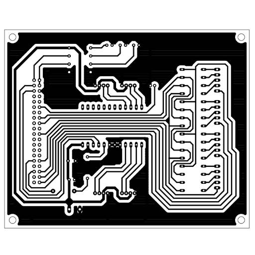
Another board view of the main board
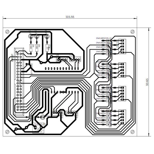
The players start a game by using the main screen which is an hdmi 5inch display connected to the raspberry pi, the UI is displayed through a web browser and game modes etc are handled by a nodejs server.
Everything is hosted on the Pi, adding a gamemode on the Git repository will trigger a pipeline on the Pi to add the new gamemode and restart everything.
ALL OF THIS FOR A BASIC LED PONG THING !
That was a fun project, I love the way the final unit looks, this is a good finished project even if not perfect.
EDIT: 2025 Louis here, the unit still works and can be used at ISEN’s Adicode space !
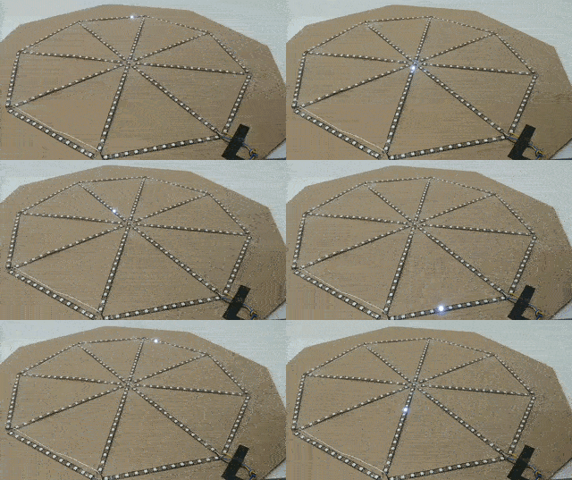
Bonus: Week 1 demo
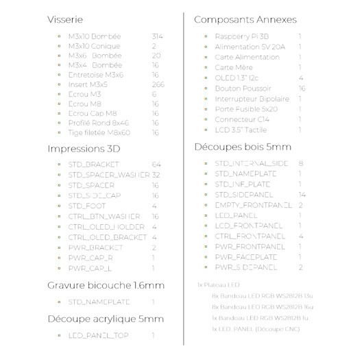
Bonus: List of the many many parts
Bonus: The logo for the OLEDs :)