USB Current Meter - Jun 2018
A little school project
DESCRIPTION
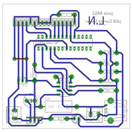
A school project, I made an USB Watmetter, it used a PIC16F73 microcontroller, a 1602 LCD display and an AD711 precision OpAmp.
USB Power was measured through a 0.02Ohm shunt resistor, input was 12v so I used a TracoPower module (I do not recall the actual part number) this is just a drop in replacement for a lm7805 but with better efficiency.
Input voltage was measured using the 12v input and a resistor divider as a reference for the resistor divider on the 5v side. This is not a good design but there are no internal vref for this pic and I did not have a better solution, the idea is that the limiting factor is the 5v traco regulator, thus if output voltage sags then it’s the 5v rail not the 12v rail if powered through a proper power supply.
This was done in order to show that I was able to use an external voltage reference on the PIC, this is an accademic project and not a proper testing device.
I am unable to find photos of the assembled board, all I have is the image of the PCB board view before applying the ground plane command.
GALLERY
An assembled board